Ⅰ. features
features
There are five major features of tokumorikun.
- A series of workflow such as path generation, laser program incorporation, motion simulation, and conversion to robot program, all in a single step.
- Can also be used online to calibrate, monitor work status, measure construction status, and modify paths according to conditions
- Various trajectory options are available for the angle of the torch relative to the construction surface, as well as for the turnaround and evacuation conditions.
- Automatic insertion of laser commands into robot JOBs, which is difficult to achieve with CAM software
- Improved productivity through reduced teaching time and more consistent weld quality
Ⅱ. Overview
Function Overview (Description)
tokumorikun has the following features.
- 1. 3D model loading
- 2. Designation of welding surface
- 3. Specify the direction and angle of dissolution
- 4. Weld Stacking Option Designation
- 5. Bead shape input
- 6. Stacking path calculation and simulation
- 7. Interference Check
- 8. real transfer
Function Overview (Reference Diagram)
This is a reference diagram and Description of the functional overview 1) to 8).
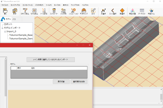
1) 3D model loading
- 3D CAD data of molds can be loaded.(Intermediate file formats such as STEP can be read)
- The position relative to the robot can be changed within the tool.
2) Designation of welding surface
- The surface to be welded can be selected visually on the screen.(Multiple selections possible)
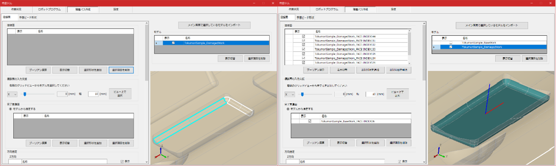
3) Designation of welding direction and orientation
- Specify a point (Vertex) on the screen to determine the direction. - Welding posture can also be specified in detail.
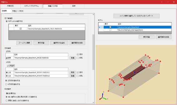
4) Weld Stacking Option Designation
- The following detailed settings are available Welding trajectory, layer calculation method, and welding sequence, Edge leaving calculations, etc...
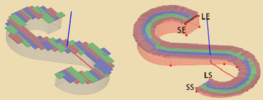
Left: Straight line welding
Right: Teaching line welding (Welding trajectory)
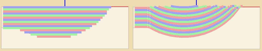
Left: Welding is done in order of height starting from the lowest point
Right: Welding is done while following the surface (layer calculation method)
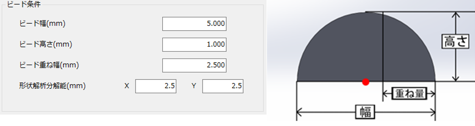
5) Bead shape input
- The width, height, overlap width, etc. of the bead shape to be stacked can be set.
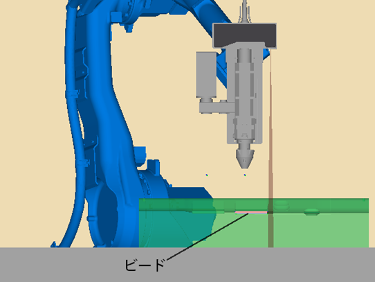
6) Stacking path calculation and simulation
- Simply select the necessary items for the lamination path and the expected bead shape can be calculated automatically. - Based on the stacking paths you have created, you can simulate them in 3D space.
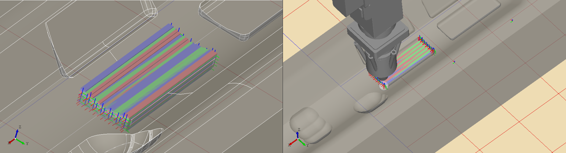
Video of stacking path calculation and simulation
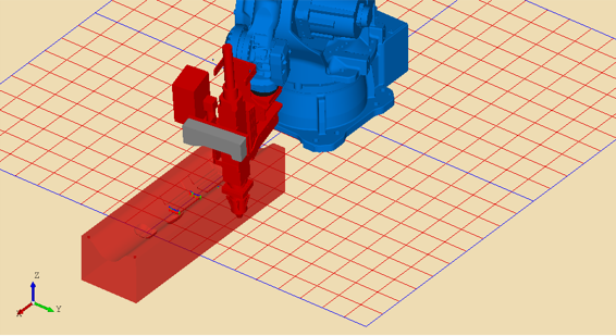
7) Interference Check
- Interference checks can be performed between the target workpiece mold and robot, beads, etc.
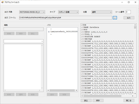
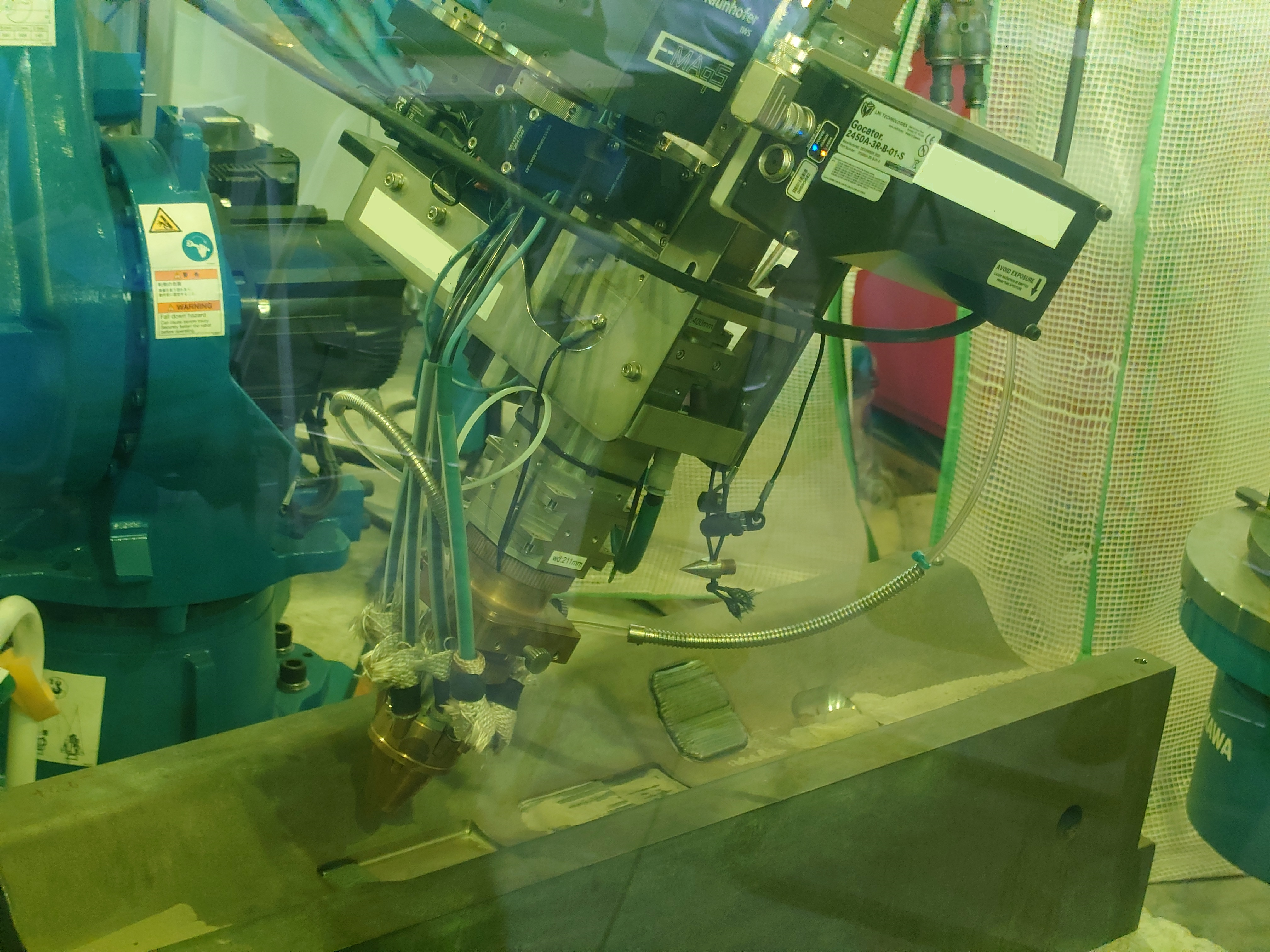
8) Transfer of actual equipment, monitoring and measurement of work status
- Robot JOBs for weld stacking can be transferred to the robot controller side. - Welding results can be checked by sensors and visual measurement jobs. After measurement, the path can be modified according to the measurement results.
Shooting posture

Shooting posture (different angle)
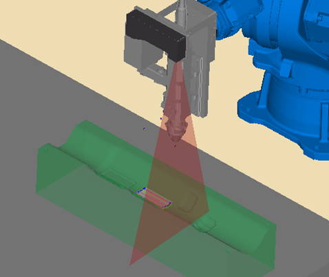
9) Measurement of actual workpiece (ScanPath) (※Option)
- The actual workpiece of the mold can be measured with a sensor and the lamination path can be calculated from there. - You can perform overlay repair on the mold from the actual product without having to prepare 3DCAD data.
Work scan
Create layered paths from scanned data
Ⅲ. Operating environment
| OS | Windows10 / 11 (64bit configuration only) |
| CPU | Intel® Core™ i7-9750H 2.6GHz (6 cores) or higher |
| memory | 32GB or more |
| Hard Disk Capacity | 1GB or more |
| graphics boat | NVIDIA Quadro T2000 Considerably more |
FAQ
Trademarks and developers
・"特盛りくん®" is a registered trademark of Nankai Mold Design Co.,Ltd. ・The developer of "特盛りくん®" is Nankai Mold Design Co.,Ltd.