Features and Functions
Features
There are five major features of RoboPath.
- It can be quickly customized to suit your application.
- Additional functions are available as an option at the customer's request. (Charged)
- Since we use OpenCASCADE (open source software), smart graphic processing is possible.
- Compatible with 5, 6, and 7-axis robots from all robot manufacturers. (There are exceptions)
- Easy to operate, Inexpensive.
Functions
RoboPath includes the following robotics features.
- Input function: tool holding, work holding mode: automatic line/circular path recognition
- Application study: robot motion range, robot joint limit, interference check, singularity detection
- Path types: Edge, Curve, Face, Weaving
- Output functions: Path vector display, Point-by-point external signal input, Animation, Calibration
- Supported robot manufacturers: All robot manufacturers' robots are supported (with some exceptions)
Ⅱ. Work Type
RoboPath has the following main corresponding work types.
- Welding (Arc Welding, Laser Welding, Spot Welding)
- Painting (Spray Painting, Thermal Spraying)
- Cutting (Laser, Water-Jet, Cut)
- Grinding (Processing of Turbine blades and Finished parts)
- Deburring, Sealing, Assembly, Palletizing, Handling
Welding
Painting
Water-jet Cut
Ⅲ. Overview
Function Overview (Description)
RoboPath has the following features.
- 1. Loading models
- You can import a CAD model of the target workpiece. Imported model(s) can be modified.
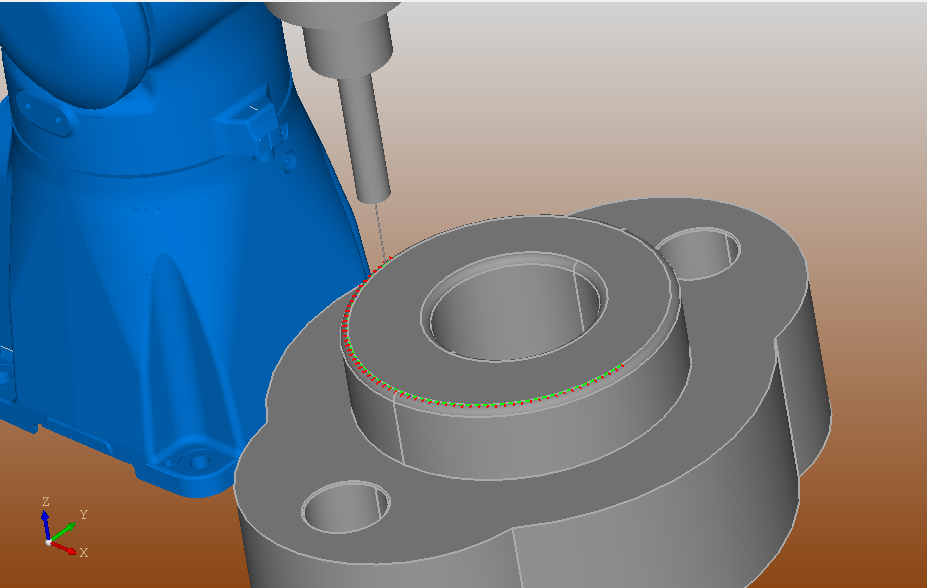
- 2. Automatic machining path creation
- You can use entities in the model (edges, lines, curves, etc.) to automatically create machining paths.
- 3. Inserting the Robot Tool
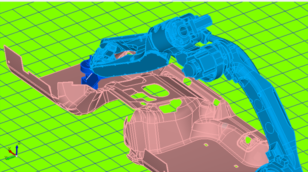
- Select the robot model and insert the robot into the screen. At the same time, the tool can be attached to the tip of the robot.
- 4. Operation simulation
- You can simulate the motion of a robot on a path, using a tool.
- 5. Automatic conversion to robot program
- Machining operations can be automatically converted to robot programs.
Function Overview (Reference Diagram)
This is a reference diagram and video of the functional overview 1) to 5).
model.png)
1) Creating and Loading models
path.png)
2) Automatic machining path creation
tool.png)
3) Inserting the Robot Tool
4) Motion simulation video
The trajectory and vector of the robot's movement are
displayed.
program.png)
5) Automatic conversion to robot program
Ⅳ. Menu bar
The following is a description of the RoboPath menu bar.
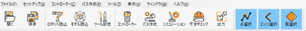
- 1) Open
- Open the file selection dialogs. Select "Target Model" to open the model file.
- 2) Saving
- Open the file dial. Enter a file name to save the model & path file.
- 3) Robot loading
- The robot loading screen will be displayed, and the target robot will be loaded from the list in the robot loading screen.
- 4) Model loading
- Select the model you want to import, and the selected CAD model will be displayed in the main screen 3D view.
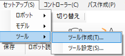
- 5) Tool settings
-
「Select "Setup", "Tools", and "Create Tool" to open the Create Tool window.
Select "Tool Settings" to load the registered tools. - 6) Controller
- A screen for calculating the forward (inverse) kinematics of the robot will be displayed, and kinematic calculations will be performed by entering the data.
- 7) Path creating
- The path creation function of this system automatically creates
paths
from the "points (vertices)", "edges", and "faces" of the CAD model.
From the main screen toolbar, check "Select Points" and "Select Edges" to select "Points (vertices)" and "Edges" from the model. You can specify the Z-axis direction by selecting a surface from the CAD model when creating a path. The Z-axis will be chosen in the direction normal to the selected surface. - 8) Simulation
- Let the robot record the motion for playback. There are two ways to record the robot's behavior: by adding the tip to the path, or by creating the path in "7) Path creation" above. The simulation screen will then be displayed.
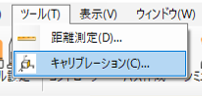
- 9) Calibration
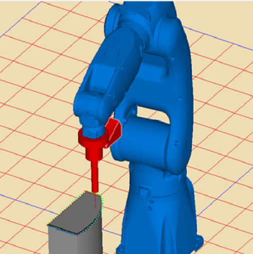
- Click on "Correct" from the main screen toolbar to display the Model Calibration screen, where you can calibrate the model path from a coordinate system consisting of three 3D view coordinates and three calibration coordinates.
- 10) Interference check
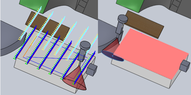
- "When the robot detects a collision with the object to be checked, it stops and the color of the collided model is highlighted in red. When a collision is detected, the robot stops and the color of the collided model is highlighted in red. The collision point will be highlighted. In addition, the collision point will be displayed. When the collision check status is set, the collision check between robots is also performed by default. In the collision check state, the collision check between robots is also performed by default.
- 11) Output
- The robot program for each robot manufacturer will be output.
Video explanation of the Menu Bar
3D view when a collision is detected.
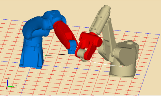
Check for interference between robots (red area is interference)
Ⅴ. Operating environment
| OS | Windows10(64bit configuration only) |
| CPU | Intel® Core™ i5 or more |
| memory |
Windows10:8GB or more |
| Hard disk capacity | 2GB or more |
FAQ